
3D-Printed Swerve Drive Pt 2

It exists! It took about a week to design, print, and assemble the swerve mechanically which is pretty good given my current situation with no tools and being stuck at home.
It’ll be a few weeks at least until I can make more physical progress on electronics because I was planning on laying out a few boards for this and won’t be able to assemble them until I find a heat gun/reflow station. I plan on having a module control board which receives a vector command over serial or CAN and then controls the module appropriately. This will involve reading the encoder position and writing rc pwm to the two motor controllers. A central board will read RC receiver commands, read the gyro over I2C, and then write the appropriate vectors to the modules.
Anyway here are some close ups of the modules
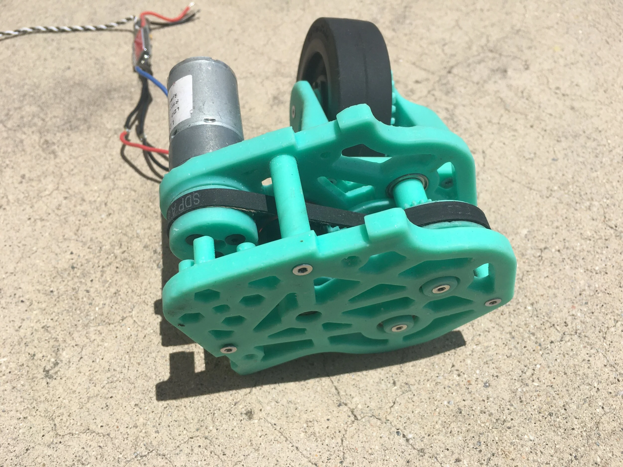
Individual assembled module

The wheel reduction uses a stage of belts, two stages of spur gears, and one stage of bevel gears, giving a total ratio of ~10:1. The pivot motor is straight 1:1 via belt with the 35:1 LDO motor.
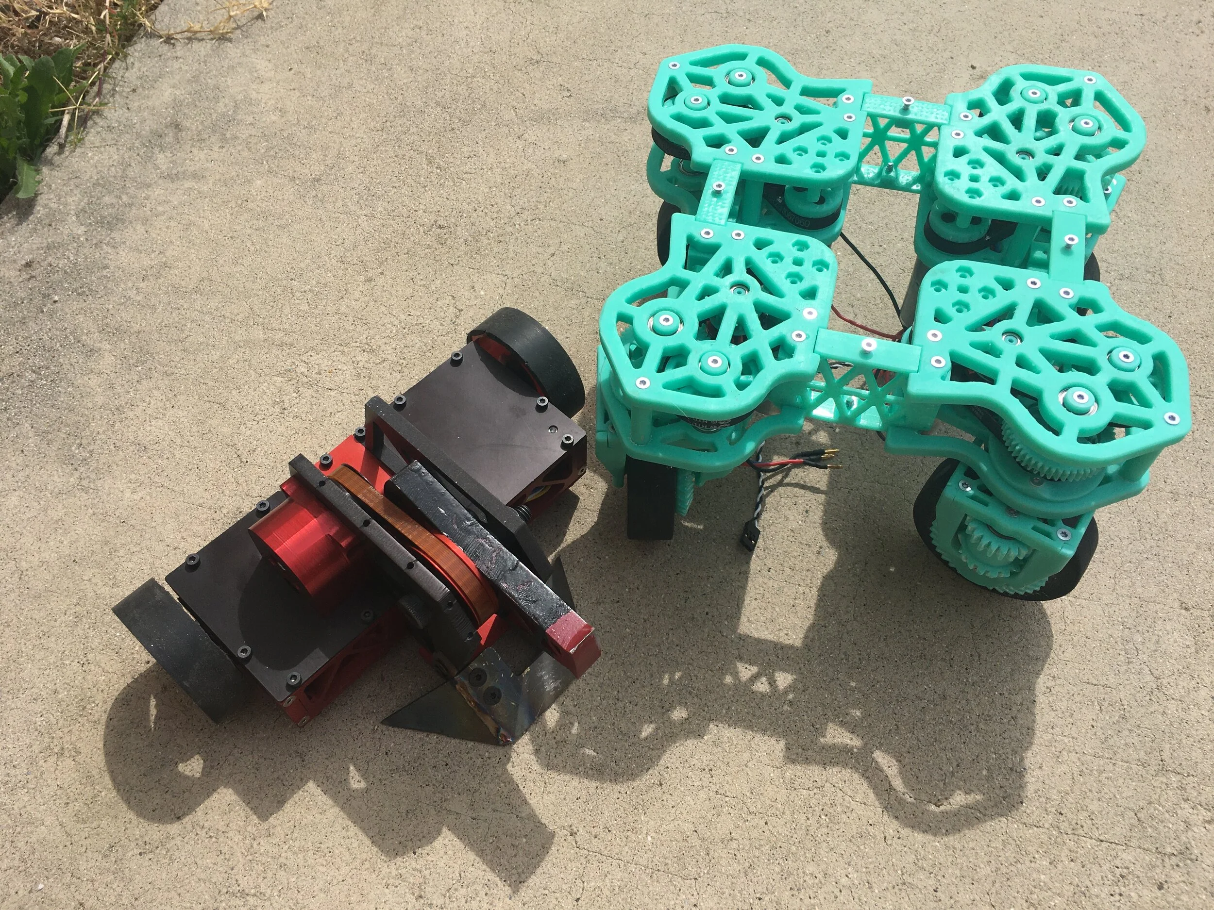
And a Baby Uppercut for scale
Short clip of gearbox being run in